GENEL ÖZELLIKLER:
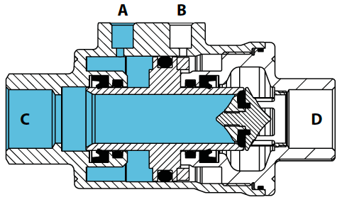
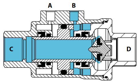
• Çift etkili 'DA' ve tek etkili 'SR’ (hem normalde açık hem de normalde kapalı) versiyonları 3/8" ila 2" boyutlarında mevcuttur.
• Tek yönlü akış.
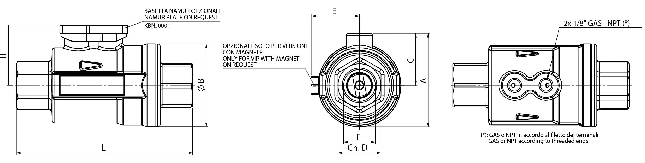
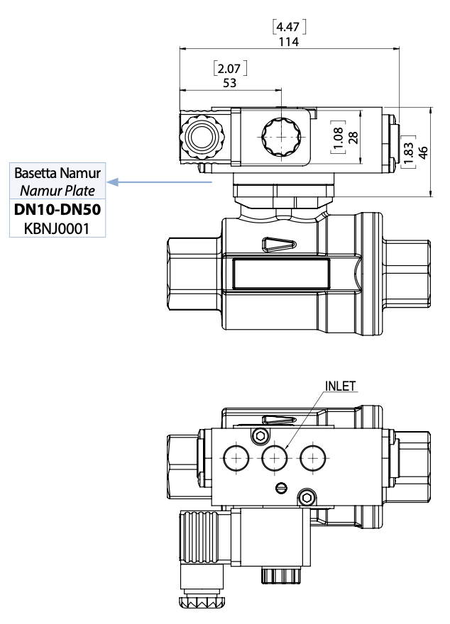
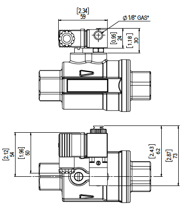
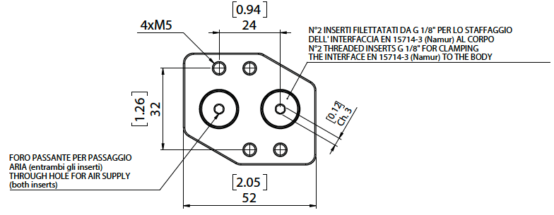
• NAMUR bağlantı tabanına uygun kontrol sıvısı bağlantıları ile (isteğe bağlı) GAS EN 10226-1 Rp (ISO 7/1) - DIN 2999 dişli bağlantılar (talep üzerine NPT diş).
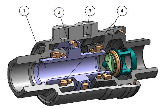
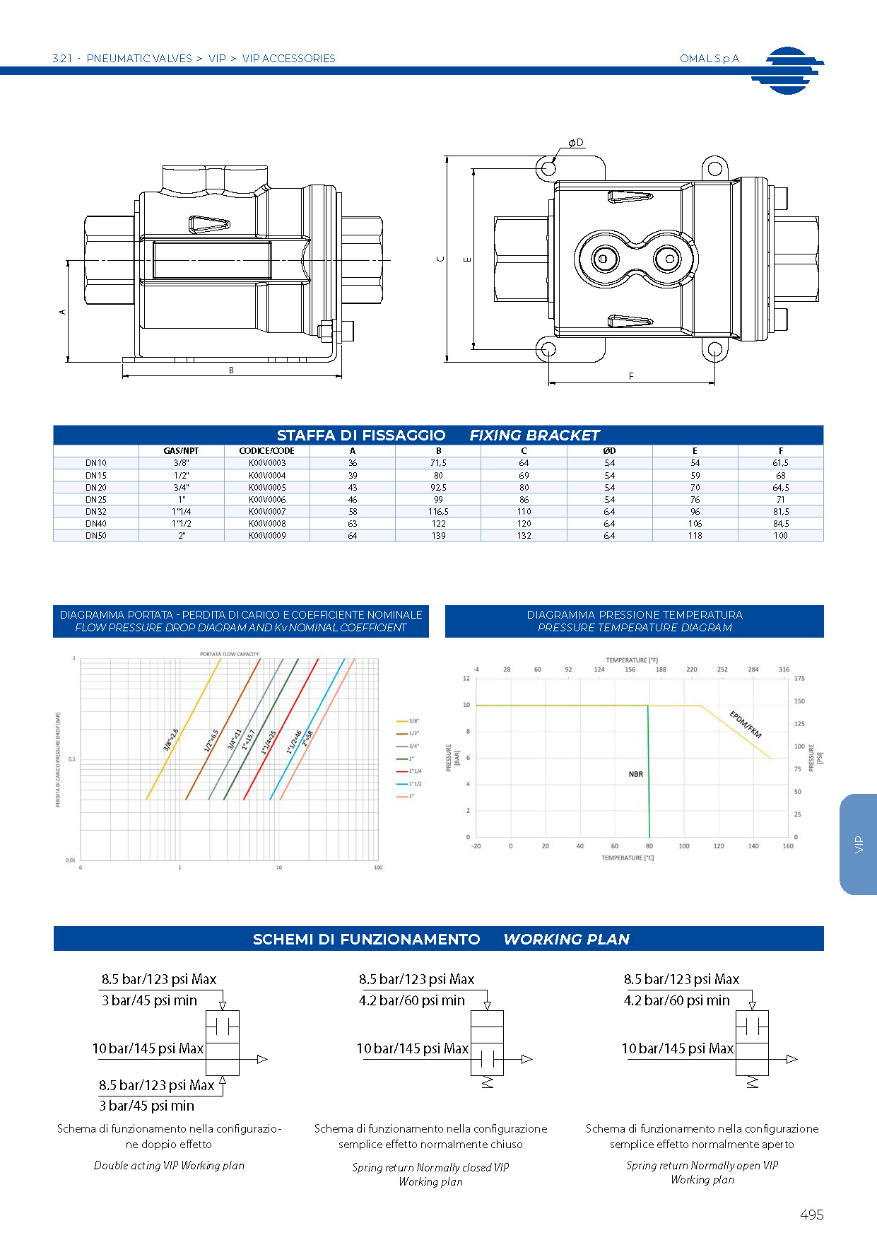
• İç akışkan dinamiklerinin optimizasyonu sayesinde kanaldaki basınç kaybı minimum düzeye indirilmiştir: akış hızı diyagramına bakınız.
• Her türlü montaj konumunda (yatay, dikey, eğik) kullanılabilir.
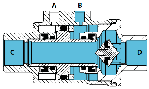
• NBR, FKM ve EPDM contalı versiyonları mevcuttur:
- NBR: hava, gazlı akışkanlar, yağlar, su vb. ile uyumludur.
- FKM: çoğu akışkan ile mükemmel uyumluluk. Buhar için tavsiye edilmez.
- EPDM: sıcak su ile mükemmel uyumluluk. Mineral ürünlerle (yağlar, gresler, vb.) uyumlu değildir.
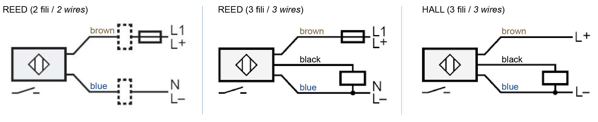
• Dahili mıknatıslı VIP versiyonu satın alınarak (sipariş sırasında belirtilmelidir), harici manyetik kontaklı endüktif sınır anahtarlarının (istek üzerine temin edilebilir) montajı aracılığıyla vananın açılıp kapandığını bildirme imkanı.
• IEC 60534-4'e göre sızdırmazlık sınıfı VI (ANSI-FCI 70-2 sınıf VI).
• Avrupa Direktifi 2014/68/EU “PED” ile uyumlu.
• ATEX 2014/34/EU konfigürasyonu sipariş sırasında talep edilmelidir.KONTROL AKIŞKANI:• Filtrelenmiş basınçlı hava (yağlanmış olması şart değildir); -20°C ila 0°C arasındaki sıcaklıklarda kuru hava kullanın.
• Yağlama yaparken, kullanılan contalarla uyumlu yağ kullanın.
• Kontrol basıncı: çift etkili versiyonlarda min. 3 bar - maks. 8,5 bar; tek etkili versiyonlarda min. 4,2 bar - maks. 8,5 bar.
AKIŞKAN TÜRÜ:• Basınç: maks. 10 bar, şemaya bakınız.
• Sıcaklık:
- NBR (mıknatıslı versiyon dahil): -20°C (-4°F) ila +80°C (176°F)
- Mıknatıssız EPDM ve FKM: -20°C (-4°F) ila +150°C (302°F)
- Mıknatıslı EPDM ve FKM: -20°C (-4°F) ila +90°C (194°F)
• Vakum sızdırmazlığı: %97 vakum (yaklaşık 30 mbar mutlak basınç, -980 mbarg). Sızıntı değeri <10-6 mbar l/s (bu değer oda sıcaklığında yılda 2 g havadan daha azdır).